
Mixture Ratio Optimization
The combustion model developed in the previous sections allows us to examine how the properties of SSME exhaust vary as a function of reactant mixture ratio. In turn, these trends provide clues that assist in selecting the optimal mixture ratio to maximize engine performance. We will begin by examining flame temperature. As shown below in Figure 3.4.1, flame temperature reaches its maximum value when $O_2$ and $H_2$ are combined at the stoichiometric mixture ratio of 8:1.
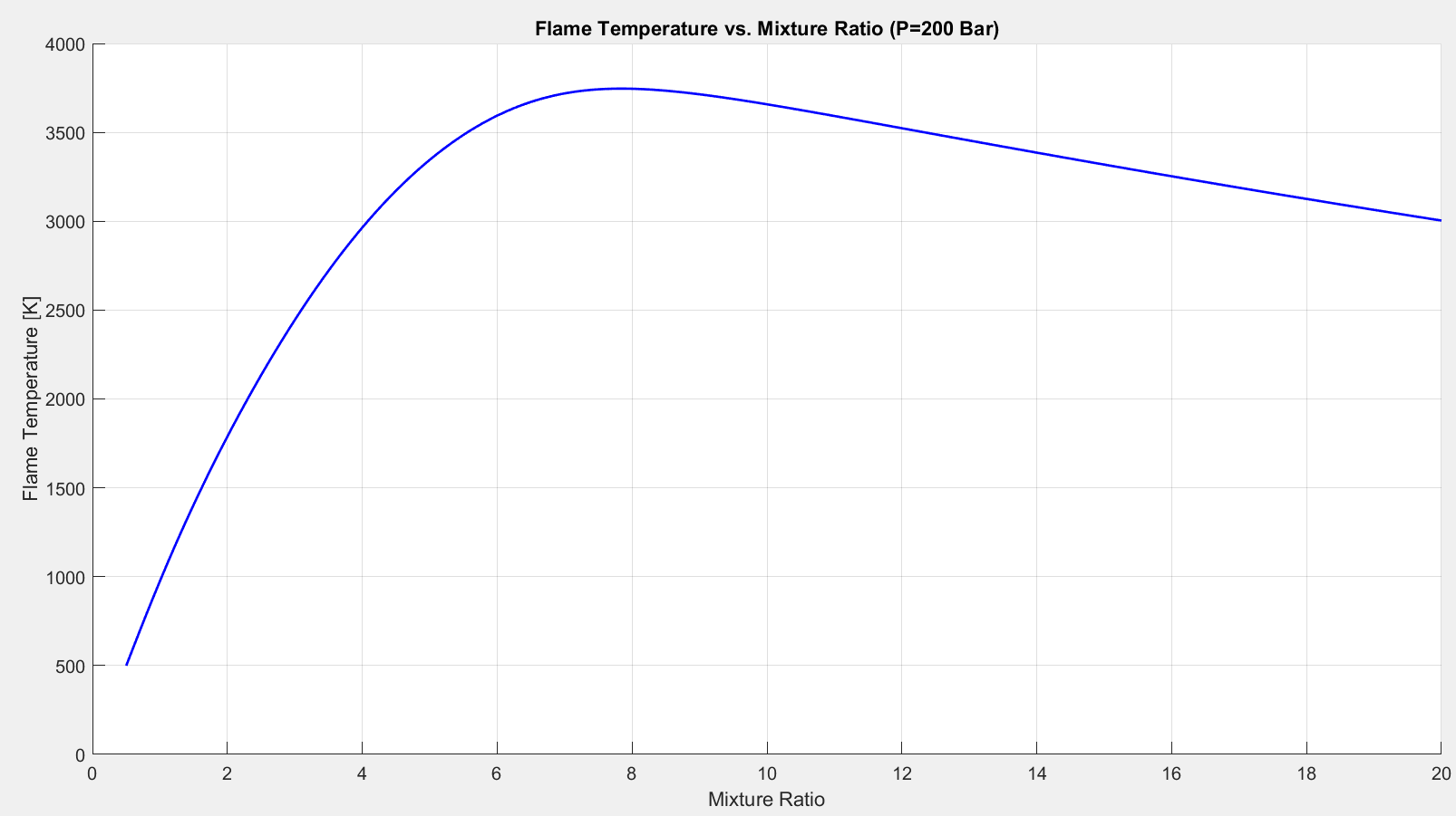
Figure 3.4.1
A rocket engine produces thrust by converting the thermal energy of the combustion products into kinetic energy as the exhaust accelerates through the nozzle. Based on this principle, it seems logical to select the stoichiometric mixture ratio to maximize the amount heat available to make this conversion. But rocket engine performance is not governed by combustion temperature alone. Exhaust gas composition plays a significant role. Exhaust composition as a function of mixture ratio is plotted below in Figures 3.4.2.
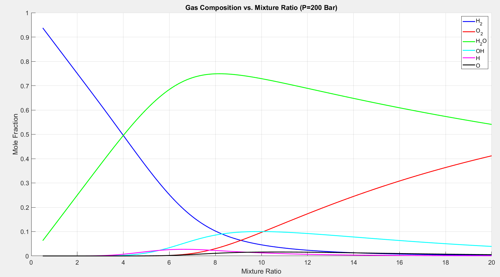
Figure 3.4.2
The stoichiometric $O_2/H_2$ reactant mixture ratio creates an exhaust gas consisting of approximately 70% water vaper, 13% diatomic hydrogen, and 17% other species by mole fraction. As the mixture ratio decreases from 8, the water vapor mole fraction decreases and the diatomic hydrogen mole fraction increases. The combustion model does not perform particularly well at predicting mole fractions for $OH$ and $H$ at mixtures ratios of less than four. Again, this error is not particularly concerning since these mole factions are very small and have little impact on the overall thermodynamic properties of the exhaust gas mixture.
On the other hand, the large mole fraction of $H_2O$ makes a significant impact on the exhaust properties. At a mixture ratio of 8 the exhaust gas is mostly water vaper and the molecular weight approaches that of water, 18 grams per mole. As the mixture ratio decreases, diatomic hydrogen becomes the predominant species and the molecular weight approaches that of $H_2$, two grams per mole. At large mixture ratios, the gas tends to consist primarily of diatomic oxygen, which causes the molecular weight to approach 32 grams per mole. This trend is plotted below on Figure 3.4.4.
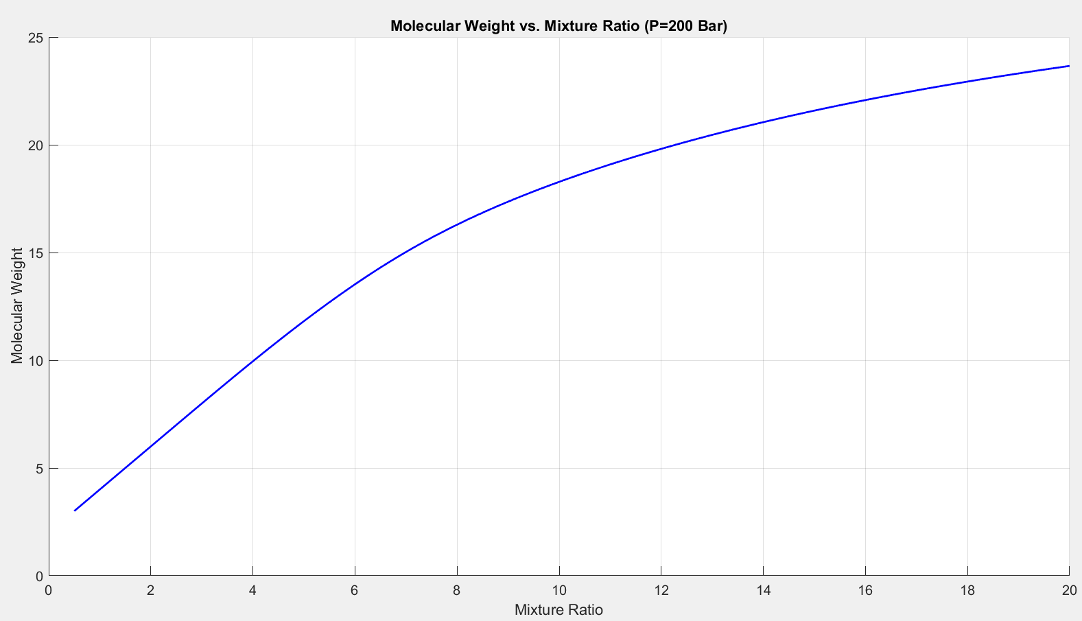
Figure 3.4.4
An important thermodynamic property directly affected by gas composition is the specific heat ratio, $\gamma$. This quantity reflects the ability of a gas molecule to store energy. Small values of $\gamma$ correspond to a high energy storage capacity.[38] The specific heat ratio is minimized at the stoichiometric mixture ratio of 8, as shown below.
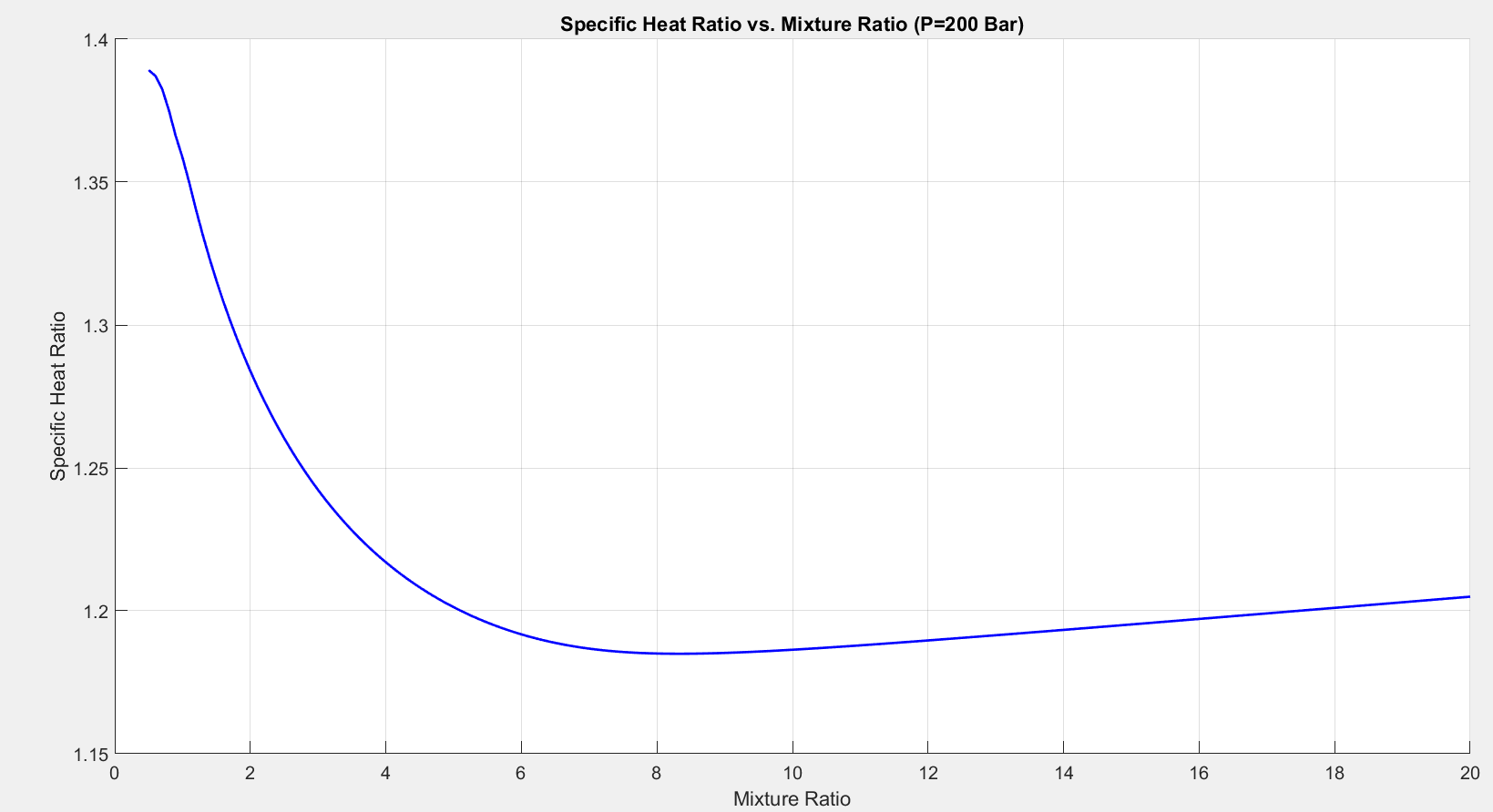
Figure 3.4.5
We are now positioned to use both molecular weight and the specific heat ratio to analyze the performance of the combustion process. This is accomplished by calculating the “characteristic velocity” produced by the combustion chamber, c* (pronounced cee-star):[38]
The following plot displays c* as a function of mixture ratio.
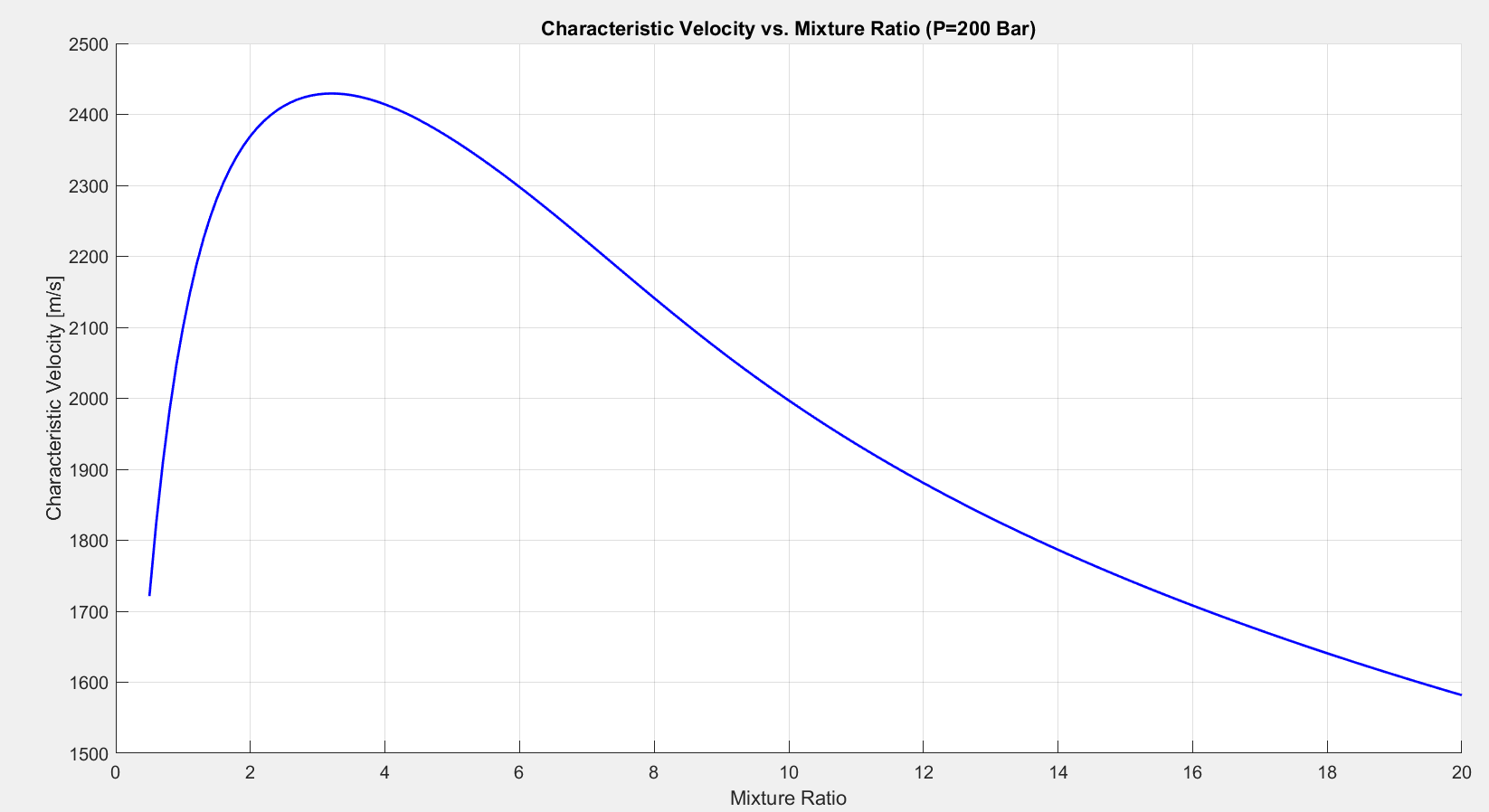
Figure 3.4.6
Figure 3.4.6 illustrates a surprising result. Characteristic velocity (i.e. combustion performance) is maximized at a mixture ratio of approximately 3.5 rather than a mixture ratio of 8 as initially suggested by Figures 3.4.1 and 3.4.5. There are two competing factors at play here: the energy of the combustion gas (controlled by flame temperature and specific heat ratio) and the molecular weight of the gas. Take a look at Equation 3.4.1. $c^*$ will be maximized when flame temperature is at its maximum (mixture ratio of 8), specific heat ratio is at its minimum (mixture ratio of 8), and the specific gas constant, $R_s$, is at its maximum. Remember that $R_s=R_u/M$, where $M$ is molecular weight. Therefore $R_s$ is maximized when molecular weight is minimized. This occurs at low mixture ratios, as shown in Figure 3.4.4. Optimal combustion performance occurs at a mixture ratio of approximately 3.5 that balances low molecular weight with a high flame temperature and a low specific heat ratio.
Combustion performance is important, but it does not quite tell the whole story. Nozzle performance must be taken into account as well. This is accomplished by calculating the engine thrust coefficient, $C_f$:[38]
In Equation 3.4.2, $\epsilon$ represents the nozzle expansion ratio (i.e. the cross-sectional area of the nozzle exit divided by the cross-sectional area of the nozzle throat). $p_e$ represents the pressure of the exhaust gas at when it reaches the nozzle exit. $p_c$ is the pressure in the combustion chamber, and $p_a$ is the ambient pressure the nozzle is exhausting into.
The $p_e-p_a$ term in Equation 3.4.2 shows that high ambient pressures reduce rocket performance. Performance would be maximized operating in vacuum where $p_a$ is zero. The $1-p_e/p_c$ term shows that nozzle performance is maximized when exit pressure is minimized. An ideal rocket nozzle would operate in vacuum and expand the exhaust to an exit pressure of zero. Exit pressure is controlled by the expansion ratio, $\epsilon$. In order to reach an exit pressure of zero, an infinite expansion ratio is required (i.e. a massive rocket nozzle with a huge exit diameter). This is clearly not practical. The Space Shuttle RS-25 Block IIA engines use an expansion ratio of 69[44] , which results in an exit pressure of approximately 20,000 Pa. This is a very small, but non-zero pressure. Combustion chamber pressure, $p_c$ in this engine is approximately 2.026*10^7 Pa (200 atm). Using this data, we can plot $C_f$ as a function of mixture ratio for both an ideal rocket nozzle (infinite expansion ratio) and the SSME with a fixed expansion ratio of 69.
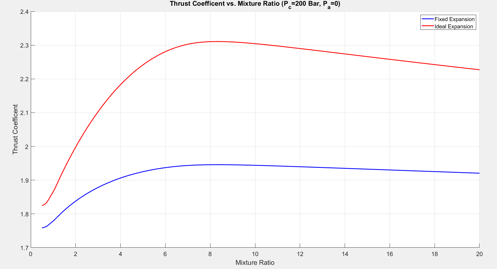
Figure 3.4.7
For both the ideal expansion and the fixed expansion, thrust coefficient is maximized at a mixture ratio of 8. This leaves us with a problem. What is the optimal mixture ratio? We could maximize nozzle performance (modeled by $C_f$) if we select a mixture ratio of 8. We could maximize combustion performance (modeled by $c^*$) by selecting a mixture ratio of 3.5. In order to resolve this contridiction, we must introduce another concept: specific impulse.
Specific Impulse
Impulse is a quantity that describes both the magnitude and duration that a force, $F$, acts upon an object. Mathematically, impulse, $I$, is described as follows:[45]
In the case of a rocket engine, the force of interest is the thrust generated by the engine. Let’s assume we are testing a miniature rocket engine that produces a constant thrust of 100 N for a duration of 5 seconds, as plotted below.
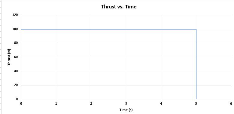
Figure 3.4.8
The amount of impulse produced during this test can be calculated utilizing Equation 3.4.3. The integral in this equation represents the area underneath the curve plotted above, which in this case is 500 $N\cdot s$.
Since this is a steady-state test, the propellent mass flow rate, $\dot m$, through the engine is constant. Let’s assume $\dot m =$ 5 kg/s, as plotted below.
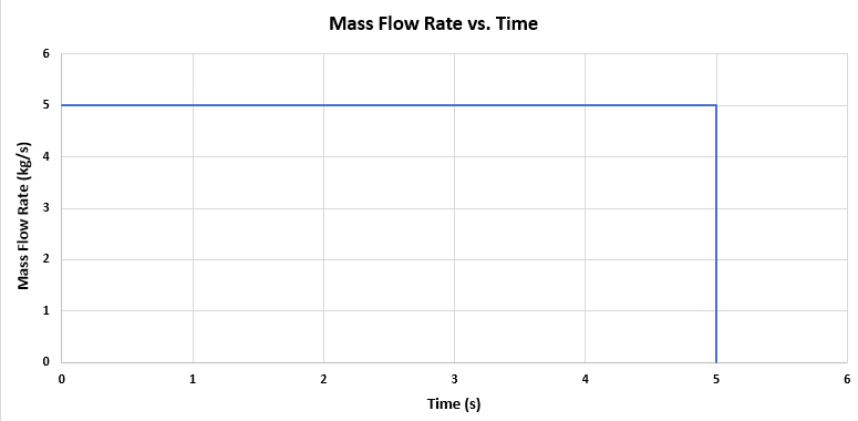
Figure 3.4.9
Specific impulse, $I_{sp}$, is defined as the total impulse, $I$, divided by the weight of propellent expended. Weight is equal to mass, m, multiplied by the acceleration of gravity, g.
The mass of propellant expended is equal to the area underneath the curve in Figure 3.4.9. This is described mathematically as follows:
In this example the area described by this integral (m) is equal to $ 5$ $kg/s \cdot 5 s = 25$ $kg$.
Utilizing Equation 3.4.4, specific impulse can then be described as:
In this example,
Looking back at Equation 3.4.6, it becomes evident that specific impulse is the ratio of thrust generated to mass of propellant expended. A highly efficient rocket engine would generate a large amount of thrust while expending very little propellant. This is the factor we will use to select the optimal mixture ratio for driving the combustion process described in the preceding sections.
The combustion model described in the previous sections is independent of nozzle design. These models only solve for combustion gas properties and do not reveal any information regarding how much thrust, $F\left(t\right)$, the rocket engine generates. The models are also independent of mass flow rate $\dot m\left(t\right)$. These are two key terms required for calculating specific impulse with Equation 3.4.6. So how can we proceed when we lack these two critical pieces of information? Fortunately $I_{sp}$ can be calculated by an alternative method utilizing data already obtained with Equations 3.4.1 and 3.4.2:[38]
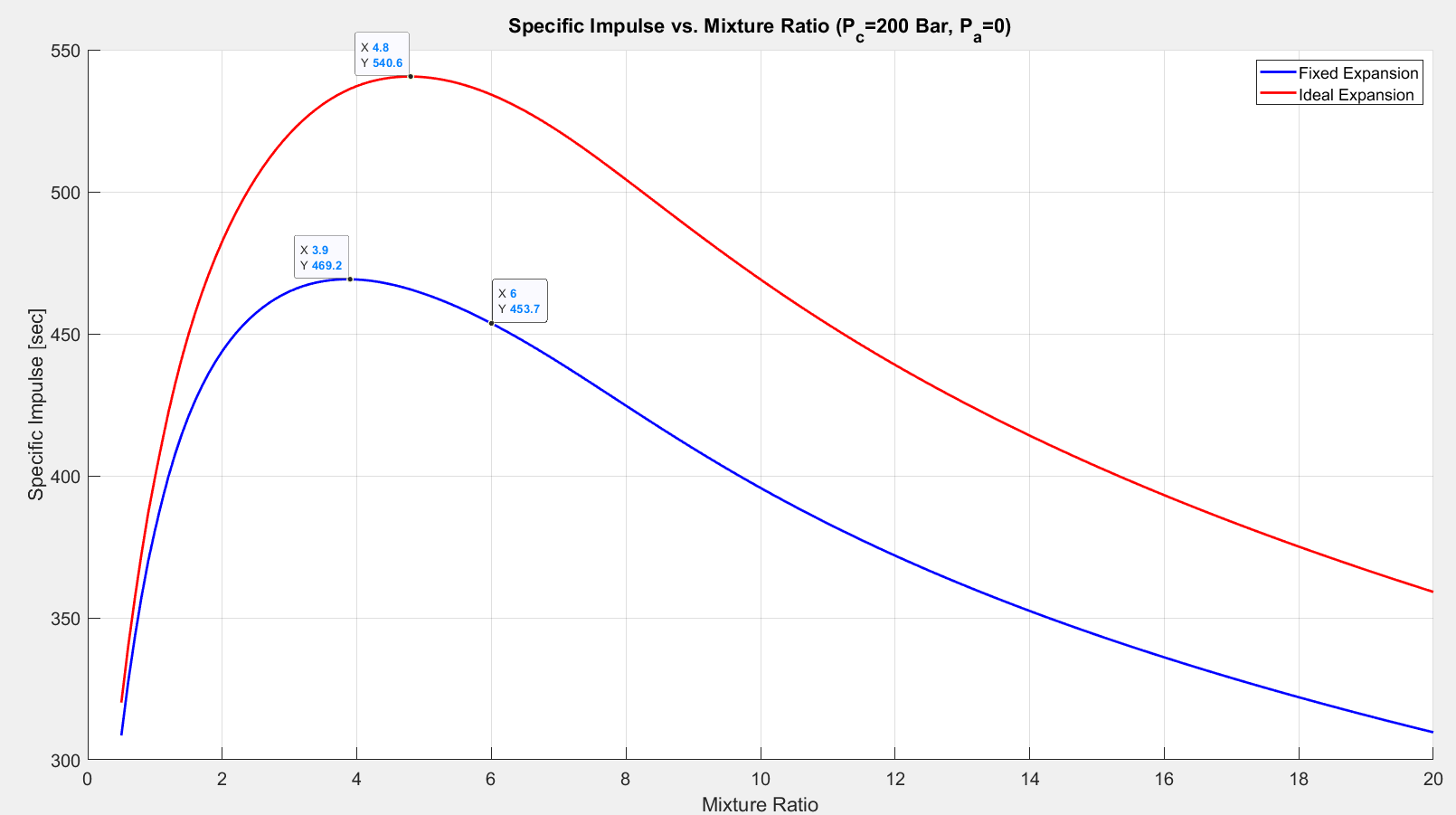
Figure 3.4.10
The curves plotted above show how specific impulse varies as a function of mixture ratio. These plots were generated under the assumption that the engine is operating in vacuum conditions. The red curve corresponds to an “ideal” expansion (i.e. infinitely large nozzle). The blue curve corresponds to real performance of the SSME utilizing an expansion ratio 69. This chart illustrates an interesting concept. The “ideal” expansion plotted above was calculated without any reference to the physical design of the engine. It shows that that chemical rocket engine performance is limited not by turbomachinery or nozzle design, but instead by the energy storage capacity and molecular weight of the propellants.[46] A rocket engine powered by liquid hydrogen and liquid oxygen is not capable of producing more than approximately 540 seconds of specific impulse.
This concept can be proven by examining the amount of energy stored within the chemical bonds of a water molecule. Let’s return our attention to the first equation introduced on the homepage of the website:
This is the fundamental reaction powering the SSME. Hydrogen and oxygen are combined to form water. Utilizing Equation 3.2.6 we can calculate the heat of formation for $H_2O$ when it is produced in the SSME main combustion chamber at a temperature of 3600 K. Performing this calculation reveals that $h_{f,H_2O}$ is 252 kJ/mol.
Now imagine this mole of water is accelerated through an “ideal” rocket engine with an infinite expansion ratio. It gains velocity and converts all 252,000 J of its chemical potential energy into kinetic energy. The kinetic energy of a particle is equal to $\frac{1}{2}mv^2$. Using this equation and the molecular weight of water (18 g/mol), the velocity, $v$, of the mole of water can be predicted when it exits the rocket engine:
Solving this equation for $v$ reveals that the mole of water has been accelerated to a velocity of 5291.5 m/s.
The amount of thrust, $F$, produced by a chemical rocket engine operating in vacuum is equal to the mass flow rate of propellant travelling through the nozzle multiplied by its exit velocity:[46]
We now have enough information to utilize Equation 3.4.6 and calculate the specific impulse of this “ideal” $H_2/O_2$ rocket engine:
Assuming steady conditions this reduces to:
This is almost identical to the maximum specific impulse predicted by the combustion model shown Figure 3.4.10. This figure indicates that optimum mixture ratio for our “ideal” $H_2/O_2$ engine is 4.5, and the optimum mixture ratio for the “real” engine is 4.0. This is close to the right answer, but there is one final factor to consider: the volume of the tanks required to store the propellants.
Tank Volume Optimization
We need several additional pieces of data to calculate the required propellant storage capacity. During lift-off it is assumed all three of the SSMEs are operating at 104.5% of their rated power level and each producing 491,000 pounds of thrust. The engines will fire continuously for 520 seconds before main engine cutoff.[2] The hydrogen and oxygen stored in the external tank have densities of 70 $kg/m^3$ and 1141 $kg/m^3$ respectively, as tabulated in Sections 1.1 and 1.2. Note that liquid hydrogen is 16 times less dense than liquid oxygen. This massive disparity in density will drive the tank volume optimization.
Using this data we can calculate the total mass of propellant needed during lift-off. The total impulse, $I$, generated during launch is calculated using Equation 3.4.3. In this case there are 3 engines each producing 491,000 pounds of thrust for 520 seconds. After calculating the total impulse generated during launch, Equation 3.4.4 can be re-arranged to solve for the total mass of propellant expended:
The total impulse, $I$ required for launch is a fixed value. Specific impulse, $I_{sp}$, is a function of mixture ratio, as previously shown. Therefore we can use Equation 3.4.8 and calculate the total propellant mass $m_{tot}$ as a function mixture ratio, $MR$. Knowing the mixture ratio allows $m_{tot}$ to be split into its hydrogen and oxygen components:
These individual masses can then be multiplied by propellant density to calculate the required volume for each storage tank. The mass and storage requirements are plotted below in Figures 3.4.11 and 3.4.12.
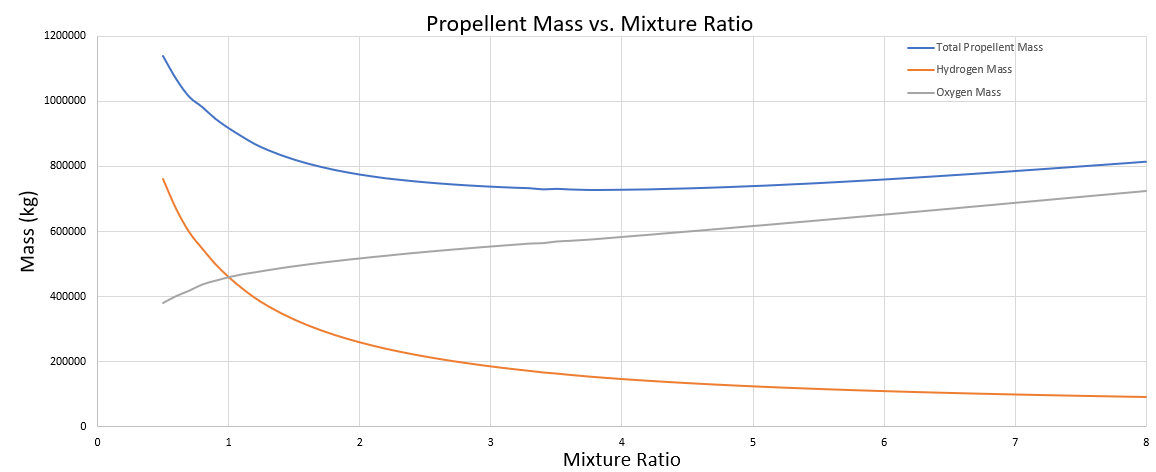
Figure 3.4.11
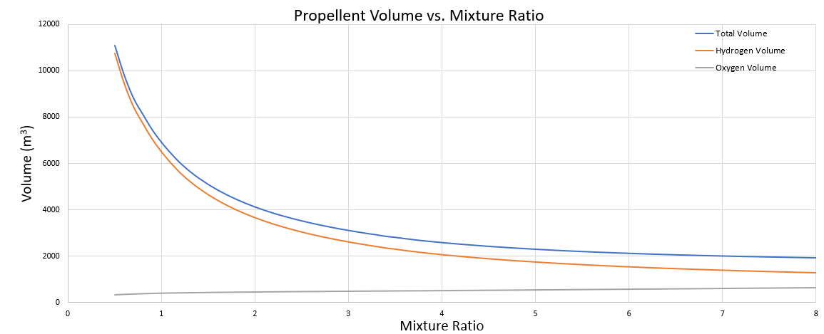
Figure 3.4.12
Figure 3.4.11 shows that total propellant mass is minimized at a mixture ratio of 4. This agrees with Figure 3.4.10 which shows that specific impulse is maximized at a mixture ratio of 4. Figure 3.4.12 shows that hydrogen storage tank volume is very sensitive to mixture ratio. Increasing the mixture ratio from 4 to 6 results in an overall tank volume reduction of 13% while only increasing the required mass of propellant by 3.5%. This increase in propellent mass can be offset by savings in the structural mass of the storage tank. Shifting the mixture ratio from 4 to 6 allows for construction of a small and lighter storage tank and may eliminate drag penalties as well.
After examining many factors NASA finally came to to chose 6 the final answer for the “optimum” mixture ratio for the SSME. The model developed here predicts that at a mixture ratio of 6.0 the engine will operate with a specific impulse of 453.7 seconds, as shown in Figure 3.4.10. The actual SSME produces a specific impulse of 452 seconds, which differs from this model’s prediction by less than 1%.